2. Institute of Aerospace Materials and Technology, Beijing 100076;
3. Shanghai Research Institute of Petrochemical Technology, Shanghai 201211, China
2. ${affiVo.addressStrCn};
3. ${affiVo.addressStrCn}
Polyacrylonitrile (PAN) based carbon fibers (denoted as CFs) have been popularly employed as reinforcements in advanced composites due to their outstanding properties, for example, high specific strength, high stiffness, low density, and design flexibility[1]. According to the forming methods of the PAN precursor fibers, CFs can be categorized into wet spun CFs and dry-jet wet spun CFs. Compared with wet spun CFs, the surface of dry-jet wet spun CFs is relatively smooth, which is beneficial to the fiber's tensile properties due to the suppressed surface defects[2]. However, the smooth surface also results in a weak bonding between the fiber and the matrix, which deteriorates the overall mechanical properties of the composites[3-6]. Therefore, an additional surface treatment of these fibers is of great importance in order to fully unleash the superior tensile properties of dry-jet wet spun CFs.
The surface treatments on wet spun CFs have been well studied over the past few decades. The commonly used methods include ionic beam irradiation, plasma treatment, and anodic oxidation[7-10]. Among these, electrochemical oxidation is usually preferred in industries because the process is chemically mild and cost effective [11-13]. For wet spun CFs, electrochemical oxidation could introduce active surface functional groups on the fiber, which chemically improves the interfacial bonding properties[14-17]. Meanwhile, this treatment can also increase the surface roughness of the fibers, which results in improved physical interlocking between the fiber and the polymer resin[15, 18]. Although the surface treatment on wet spun CFs is well studied [11, 18-20], few reports have been found on studying the surface modification of dry-jet wet spun CFs. Furthermore, the mechanism of improving the interlayer strength of dry-jet wet spun CFs has not been thoroughly studied.
In this study, the surface of dry-jet wet spun CFs was continuously oxidized in an ammonium bicarbonate (NH4HCO3) aqueous solution. The effects of treatment time and current density on the mechanical properties of CFs were studied. Fourier transform infrared spectroscopy (FT-IR), X-ray photoelectron spectroscopy (XPS), scanning electron microscopy (SEM), atomic force microscope (AFM) were applied to study the effects of the surface structures and morphologies on the mechanical properties of electrochemically modified dry-jet wet spun CFs. The crystal structure of the fiber was obtained by wide angle X-ray diffraction (XRD). Finally, grey relational degree method was used to calculate and identify the significant influencing factors (electrolysis time and current density).
1 Experimental 1.1 MaterialsDry-jet wet pun carbon fibers (12 000 filaments per tow, T700 grade)were prepared in lab without any previous surface treatment. NH4HCO3 and triethylenetetramine were provided by Beijing Tongguang Fine Chemical Co. Ltd. Epoxy resin E-44 was provided by Bluestar New Material Wuxi Resin Factory. Acetone was provided by Beijing Chemical Works.
1.2 Preparation of samplesCarbon fibers, serving as the anode, were continuously fed into aqueous solution of NH4HCO3. The treatment times were set from 0 to 150 s. The electric current densities were set as 0, 2.11, 3.86, 5.27, 7.02 A/m2. The NH4HCO3 concentration of 1 mol/L is identified as the proper processing parameter based on previous experiments[13]. After the oxidation, the samples were continuously washed with deionized water and dried at 105 ℃ for 150 s, respectively.
For the composite samples used for interlaminar shear strength test composite, epoxy resin E-44 was used as matrix resin and triethylenetetramine was used as curing agent. After thorough stirring, the resin and fiber were quickly coated on the surface of carbon fiber to fully infiltrate as far as possible. Similarly, for tensile strength test, epoxy resin E-44, acetone and triethylenetetramine were used to prepare composites.
1.3 CharacterizationFourier transform-infrared spectroscopy was tested by Nicolet 8700 spectrometer (American Thermal Power Company). The carbon fibers were cut into powder, and then dried at 70 ℃ for 2 hours. Carbon fibers were then mixed with KBr at a mass ratio of 40:1. The scanning range was 400-4 000 cm-1.
The quantitative analysis of surface elements and functional groups of carbon fibers was mainly carried out by X-ray photoelectron spectroscopy. Thermo VG ESCALAB250 (Thermo Scientific, UK) X-ray photoelectron spectrometer was used. The test ray source was MgKα (1 253.6 eV) and the power was 250 W (12.5 kV×20 mA).
The fiber was glued on the sample table by conductive adhesive without spraying gold.The surface morphology of carbon fiber before and after treatment was examined by scanning electron microscopy (Hitachi S-4700, Japan).
The topographical images of the surface of carbon fiber were obtained by Dimension 3100 V atomic force microscopy (AFM) (Veeco, US) in a tapping mode and the surface roughness was also calculated by AFM.
D/MAX2500 VB2+/PC diffractometer (Rigaku, Japan) with a ray wavelength of 0.154 18 nm was used to obtain the crystal structure of the fiber. The test tube pressure was 40 kV and the test tube flow was 200 mA.
The interlaminar shear strength (ILSS) and the tensile strength (TS) of carbon fibers were tested using Instron 5567 universal testing machines(Instron, US) based on GB 3357—82[21] and GB/T 3362—2017[22], respectively.
1.4 CalculationGrey relational degree is calculated by the steps listed below.
1) Initial value, interval relative value or mean value are used to conduct dimensionless processing on the original data. In general, averaging is more suitable for processing data without obvious ascending or descending trend.
| $ \boldsymbol{X}^{(0)}=\left|\begin{array}{cccc} X_1^{(0)}(1) & X_1^{(0)}(2) & \cdots & X_1^{(0)}(M) \\ X_2^{(0)}(1) & X_2^{(0)}(2) & \cdots & X_2^{(0)}(M) \\ \vdots & \vdots & \vdots & \vdots \\ X_N^{(0)}(1) & X_N^{(0)}(2) & \cdots & X_N^{(0)}(M) \end{array}\right| $ | (1) |
If averaging is adopted, then
| $ \begin{aligned} &X_i^{(0)}=\frac{\sum\limits_{i=1}^N X_i^{(0)}(t)}{M} \quad(t=1, 2, \cdots, N) \\ &X_i^{(1)}(t)=\frac{X_i^{(0)}}{X_i^{(0)}(t)} \quad(t=1, 2, \cdots, N) \end{aligned} $ | (2) |
The data obtained after averaging can still be written in the form of matrix.
| $ \boldsymbol{X}^{(1)}=\left|\begin{array}{cccc} X_1^{(1)}(1) & X_1^{(1)}(2) & \cdots & X_1^{(1)}(M) \\ X_2^{(1)}(1) & X_2^{(1)}(2) & \cdots & X_2^{(1)}(M) \\ \vdots & \vdots & \vdots & \vdots \\ X_N^{(1)}(1) & X_N^{(1)}(2) & \cdots & X_N^{(1)}(M) \end{array}\right| $ | (3) |
2) Record the reference sequence Xi(1)(t) and Xj(1)(t) and calculate the absolute difference between the two corresponding points.
| $ \varDelta_{i j}(t)=\left|X_i^{(1)}(t)-X_j^{(1)}(t)\right| \quad(j=2, \cdots, N ; j \neq \\ \text { 1) } $ | (4) |
Find the minimum value Δmin and maximum value Δmax of Δij(t), and then calculate the correlation coefficient Lij(t) of the reference sequence and the comparison sequence of each point.
| $ L_{i j}(t)=\frac{\varDelta_{\min }+\varDelta_{\max }}{\varDelta_{i j}(t)+k \times \varDelta_{\max }} \quad k \in[1, 2] $ | (5) |
3) Calculate the correlation degree Rij of the comparison sequence and the reference sequence.
| $ R_{i j}=\frac{\sum\limits_{t=1}^M L_{i j}(t)}{M} \quad(j=1, 2, \cdots, N) $ | (6) |
4) Arrange the obtained Rij from large to small, and the correlation ranking can be obtained, and the influence of the larger Rij in the reference sequence is greater than the smaller Rij.
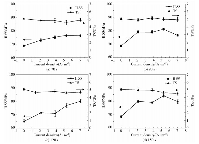
2 Results and discussion 2.1 Mechanical propertyThe effect of electrochemical modification on the interfacial bonding strength between the dry-jet wet spun CFs and the epoxy resin is evaluated using an ILSS test. Fig. 1(a)-(d) show the ILSS and TS of CFs as a function of current density and treatment time. It is shown that the ILSS of CFs is enhanced by increasing oxidation current density until 5.27 A/m2. Meanwhile, at high current density, large amounts of air bubbles emerge on the surface of CFs, indicating that the electrochemical reaction is violent at this condition.
|
Fig.1 The interlaminar shear strength and tensile strength of carbon fibers as a function of treatment current density at different treatment times |
The highest ILSS value of 84 MPa is achieved for CFs with a treatment time of 150 s and a current density of 5.27 A/m2, which is a 21.7% enhancement compared with the ILSS of CFs without any treatment. In general, the ILSS of dry-jet wet spun CFs can be successfully enhanced while maintaining the standard TS of around 4.9 GPa, indicating the effectiveness of the electrochemical oxidation on improving the interfacial bonding between the fiber and the matrix while retaining the structural integrity of the fiber.
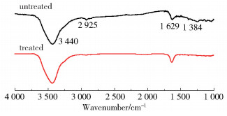
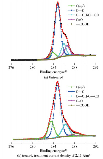
2.2 Chemical compositionFig. 2 shows the FT-IR spectra of the CFs before and after modification. No new peak formed or disappeared after treatment, indicating that the electrochemical treatments do not alter the types of functional groups on the surface of the CFs. XPS measurements were carried out to quantitatively analyze the functional groups on the surface of CFs. The C1s curves in the XPS spectra were further deconvoluted into four subpeaks associated with the carbon atoms in the functional groups of C—OH/O—CO, C=O, and —COOH, as shown in Fig. 3.
|
Fig.2 FT-IR spectra of CFs before and after treatment |
|
Fig.3 XPS spectra of CFs before and after treatment |
The percentages of these oxygen-containing functional groups are summarized in Table 1. The content of —COOH significantly increases from 0.10% to 5.10% after surface treatment. Meanwhile, the increase of the —COOH content is accompanied by the decrease of —OH, and C=O contents. It can be presumed that the increase of —COOH content is due to two reasons: ① the surface carbon atoms are partially oxidized (corresponding to the decrease of the C—C content from the XPS results); ② the —OH and/or C=O groups are oxidized to yield —COOH groups (corresponding to the decrease of the C=O and C—C contents from the XPS results). The increase of —COOH groups enhances the wettability and the chemical affinity between the treated CFs and epoxy resin, which is accounted for the improved ILSS of the composites. What is more, after the initial electrochemical treatment, the —OH functional group is oxidized to C=O. And then, with the increase of current density, part of C—C will be converted into —OH, resulting in the increase of —OH content.
| 下载CSV Table 1 Percentages of several oxygen-containing functional groups on the surfaces of CFs before and after electrochemical oxidation treatment for 120 s |
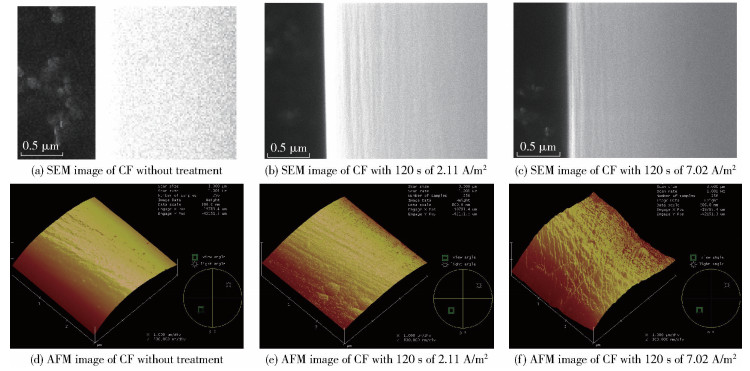
SEM and AFM were employed to examine the surface morphologies of the CFs before and after electrochemical treatment. As shown in Fig. 4, compared with the smooth surface of untreated CFs, narrow grooves are found on the surface of CFs with treatment for 120 s. The roughness values (Ra) of the fibers with 120 s treatment (Fig. 4(e) and Fig. 4(f)) are 63 nm and 69 nm, respectively, while the Ra of the untreated component (Fig. 4(d)) is 43 nm. The increased surface roughness after electrochemical oxidation treatment is believed to enhance the mechanical interlocking between the fiber and the resin matrix, which is favorable for improving interfacial adhesion.
|
Fig.4 SEM and AFM images of CFs before and after treatment |
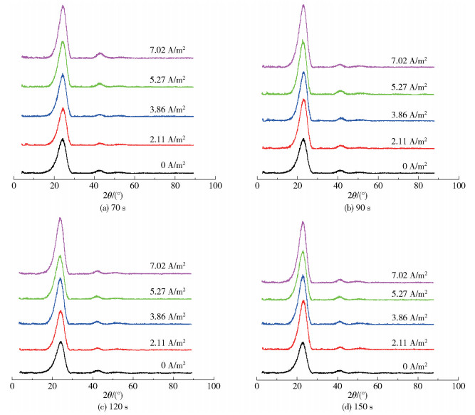
X-ray diffraction can be used to analyze the change of microcrystalline size of the fibers after surface treatment. Fig. 5 shows the XRD spectra of CFs before and after modification. No new peak formed or disappeared after treatment, indicating that the electrochemical treatments do not alter the microcrystalline type of the CFs. The half peak width β1/2 and diffraction angle θ of each diffraction peak were calculated. The diffraction peak at about 2θ=25° represents the crystal planes (002) in the turbostratic graphitic structure. The crystallite sizes of samples which are treated for 70 s are listed in Table 2, where Lc represents the thickness of the microcrystals and Id represents the current density. As can be seen in Table 2, there is no obvious change of Lc and d002(the layer spacing of the crystal planes (002)), indicating the surface modification do not alter the bulk crystalline structure of CFs.
|
Fig.5 XRD spectra of CFs before and after modification |
| 下载CSV Table 2 Values of crystallite sizes for carbon fibers which are treated for 70 s |
Finally, grey relational degree method is used to calculate and identify the significant influencing factors. The numerical relationship between various factors (such as the electrolysis time, current density, tensile strength and interlaminar shear strength) in the system can be obtained through calculation.
The values in Fig. 1 are used to calculate the grey relational degree. Tensile strength and interlaminar shear strength are taken as the reference sequence Xi(0), current density and electrolytic time are taken as the comparison sequence Xj(0). Then, a 2×12 matrix can be listed as follows.
| $ \boldsymbol{X}_j^{(0)}=\left|\begin{array}{cccccccccccc} 70 & 90 & 120 & 150 & 70 & 90 & 120 & 150 & 70 & 90 & 120 & 150 \\ 1.40 & 1.40 & 1.40 & 1.40 & 3.51 & 3.51 & 3.51 & 3.51 & 7.38 & 7.38 & 7.38 & 7.38 \end{array}\right| $ | (7) |
The reference sequence consists of a 2×12 matrix
| $ \boldsymbol{X}_i^{(0)}=\left|\begin{array}{llllllllllll} 5.06 & 5.00 & 4.66 & 5.03 & 4.94 & 4.90 & 4.61 & 4.72 & 4.57 & 4.65 & 4.57 & 4.38 \\ 72.1 & 79.6 & 77.1 & 83.8 & 72.0 & 74.2 & 72.4 & 84.2 & 78.4 & 77.7 & 76.2 & 78.6 \end{array}\right| $ | (8) |
Both Xj(0) and Xi(0) are processed by equation (2). The calculation is listed below.
| $ \begin{aligned} \boldsymbol{X}_j^{(0)} &=\left|\begin{array}{c} 107.5 \\ 4.0967 \end{array}\right| \boldsymbol{X}_i^{(0)}=\left|\begin{array}{c} 4.7575 \\ 77.1925 \end{array}\right| \\ \boldsymbol{X}_j^{(1)} &=\left|\begin{array}{lllllll} 1.5357 & 1.1944 & 0.8958 & \cdots & 1.1944 & 0.8958 & 0.7167 \\ 2.9262 & 2.9262 & 2.9262 & \cdots & 0.5551 & 0.5551 & 0.5551 \end{array}\right| \end{aligned} $ | (9) |
| $ \boldsymbol{X}_i^{(1)}=\left|\begin{array}{lllllll} 0.9402 & 0.9515 & 1.0209 & \cdots & 1.0231 & 1.0410 & 1.0862 \\ 1.0712 & 0.9701 & 1.0003 & \cdots & 0.9931 & 1.0137 & 0.9822 \end{array}\right| $ | (10) |
A 2×12 matrix can be formed from the absolute difference between the reference sequence and the comparison sequence of the corresponding point tensile strength as follows.
| $ \boldsymbol{\varDelta}_{i j}^{(1)}(t)=\left|\begin{array}{lllllll} 0.5955 & 0.2429 & 0.1251 & \cdots & 0.1713 & 0.1452 & 0.3695 \\ 1.9860 & 1.9747 & 1.9053 & \cdots & 0.4680 & 0.4859 & 0.5311 \end{array}\right| \\ \begin{aligned} &\varDelta_{\min }^{(1)}=0.1351 \\ &\varDelta_{\max }^{(1)}=1.9860, k=1 \end{aligned} $ | (11) |
According to equation (5), Lij(1)(t) is obtained as below.
| $ \boldsymbol{L}_{i j}^{(1)}(t)=\left|\begin{array}{lllllll} 0.6050 & 0.8594 & 1.0000 & \cdots & 0.9397 & 0.9729 & 0.7467 \\ 0.5340 & 0.5355 & 0.5451 & \cdots & 0.8644 & 0.8581 & 0.8427 \end{array}\right| $ | (12) |
Then, the correlation degree of comparison series on the tensile strength of dry-jet wet spun carbon fiber can be obtained by equation (6). The calculation of electrolysis time (0.829 4) is larger than that of current density (0.791 8). Similarly, the correlation degree of the ILSS of dry-jet wet spun CF/epoxy resin composite was ranked as follows: electrolysis time (0.830 3), current density (0.790 2). The calculation shows that the main factor that affects the tensile strength and the interlaminar shear strength of carbon fibers is electrolysis time.
3 ConclusionElectrochemical oxidation based on NH4HCO3 solution is an effective method for surface treating of dry-jet wet spun CFs. The ILSS of CFs is greatly improved from 69 MPa to 84 MPa with a treatment time of 150 s and a current density of 5.27 A/m2. The characterization of the chemical and morphological structures on the fiber surface reveals that the enhancement of ILSS is due to the optimization of both the chemical and physical structure: (1) the electrochemical treatment can add additional oxygen containing functional groups to improve the bonding between the CFs and the epoxy resin; (2) the oxidation of edge carbon atoms on the fiber surface can increase the surface roughness, allowing a greater degree of mechanical interlocking between the fiber and the matrix.
In addition, the result of the grey correlation degree method shows that the electrolysis time and current density are the main factors affecting the tensile strength and interlaminar shear strength of dry-jet wet spun carbon fiber during surface treatment, while the electrolysis time shows a bigger impact than the current density.
| [1] |
KAFI A, LI Q X, CHAFFRAIX T, et al. Surface treatment of carbon fibres for interfacial property enhancement in composites via surface deposition of water soluble POSS nanowhiskers[J]. Polymer, 2018, 137: 97-106. DOI:10.1016/j.polymer.2018.01.016 |
| [2] |
OLSSON C, SJOHOLM E, REIMANN A. Carbon fibres from precursors produced by dry-jet wet-spinning of kraft lignin blended with kraft pulps[J]. Holzforschung, 2017, 71(4): 275-283. DOI:10.1515/hf-2016-0189 |
| [3] |
MIYAZAKKI T, MATSUNAMI C, SHIROSAKI Y. Bioactive carbon-PEEK composites prepared by chemical surface treatment[J]. Materials Science & Engineering C-Materials for Biological Applications, 2017, 70: 71-75. |
| [4] |
WAN Y J, GONG L X, TANG L C, et al. Mechanical properties of epoxy composites filled with silane-functionalized graphene oxide[J]. Composites Part A: Applied Science and Manufacturing, 2014, 64: 79-89. DOI:10.1016/j.compositesa.2014.04.023 |
| [5] |
XU Z L, YANG T, NAKAMURA M, et al. Effect of carbon powder surface treatment on carbon fiber reinforced PA composites[J]. Energy Procedia, 2016, 89: 15-23. DOI:10.1016/j.egypro.2016.05.003 |
| [6] |
CHEN H, CAI Q Y, WU J, et al. Interfacial enhancement of carbon fiber/nylon12 composites by grafting nylon 6 to the surface of carbon fiber[J]. Applied Surface Science, 2018, 441: 538-545. DOI:10.1016/j.apsusc.2018.01.158 |
| [7] |
BOROOJ M B, SHOUSHTARI A M, HAJI A, et al. Optimization of plasma treatment variables for the improvement of carbon fibres/epoxy composite performance by response surface methodology[J]. Composites Science and Technology, 2016, 128: 215-221. DOI:10.1016/j.compscitech.2016.03.020 |
| [8] |
LEE H, OHSAWA I, TAKAHASHI J. Effect of plasma surface treatment of recycled carbon fiber on carbon fiber-reinforced plastics (CFRP) interfacial properties[J]. Applied Surface Science, 2015, 328: 241-246. DOI:10.1016/j.apsusc.2014.12.012 |
| [9] |
LU W B, WANG C G, YUAN H. Liquid-phase oxidation modification of carbon fiber surface[C]//International Conference on Frontiers of Advanced Materials and Engineering Technology (FAMET). Xiamen, 2012: 2008-2012.
|
| [10] |
田艳红, 魏旭峰, 张学军. 电泳沉积海藻酸钠/碳纳米管修饰高模碳纤维表面[J]. 北京化工大学学报(自然科学版), 2022, 49(3): 16-21. TIAN Y H, WEI X F, ZHANG X J. Surface modification of high-modulus carbon fibers by electrophoretic deposition of sodium alginate/carbon nanotubes[J]. Journal of Beijing University of Chemical Technology (Natural Science), 2022, 49(3): 16-21. |
| [11] |
ZHAO X D, XIONG D S, WU X X. Effects of surface oxidation treatment of carbon fibers on biotribological properties of CF/PEEK materials[J]. Journal of Bionic Engineering, 2017, 14: 640-647. DOI:10.1016/S1672-6529(16)60430-4 |
| [12] |
CHEN J, YU S, XIONG X. The effect of surface electrolytic treatment on carbon fibers and the microstructure of pyrocarbon around it during chemical vapor deposition[J]. Solid State Sciences, 2013, 25: 124-129. DOI:10.1016/j.solidstatesciences.2013.08.014 |
| [13] |
LIU J, TIAN Y L, CHEN Y J, et al. A surface treatment technique of electrochemical oxidation to simultaneously improve the interfacial bonding strength and the tensile strength of PAN-based carbon fibers[J]. Materials Chemistry and Physics, 2010, 122: 548-555. DOI:10.1016/j.matchemphys.2010.03.045 |
| [14] |
WOODHEAD A L, DE SOUZA M L, CHURCH J S. An investigation into the surface heterogeneity of nitric acid oxidized carbon fiber[J]. Applied Surface Science, 2017, 401: 79-88. DOI:10.1016/j.apsusc.2016.12.218 |
| [15] |
SHARMA M, GAO S L, MÄDER E, et al. Carbon fiber surfaces and composite interphases[J]. Composites Science and Technology, 2014, 102: 35-50. DOI:10.1016/j.compscitech.2014.07.005 |
| [16] |
FEIH S, MOURITZ A P. Tensile properties of carbon fibres and carbon fibre-polymer composites in fire[J]. Composites Part A: Applied Science and Manufacturing, 2012, 43: 765-772. DOI:10.1016/j.compositesa.2011.06.016 |
| [17] |
刘杰, 王春华, 白艳霞, 等. 碳纤维的电化学表面改性及其表面结构演变[J]. 北京化工大学学报(自然科学版), 2012, 39(5): 79-86. LIU J, WANG C H, BAI Y X, et al. Electrochemical surface treatment and surface structure evolution of polyacrylonitrile-based carbon fibers[J]. Journal of Beijing University of Chemical Technology (Natural Science), 2012, 39(5): 79-86. |
| [18] |
DONG J D, JIA C Y, WANG M Q, et al. Improved mechanical properties of carbon fiber-reinforced epoxy composites by growing carbon black on carbon fiber surface[J]. Composites Science and Technology, 2017, 149: 75-80. DOI:10.1016/j.compscitech.2017.06.002 |
| [19] |
ALLRED R E, WESSON S P, SHIN E E, et al. The influence of sizings on the durability of high-temperature polymer composites[J]. High Performance Polymer, 2004, 15: 395-419. |
| [20] |
ANDIDEH M, ESFANDEH M. Effect of surface modification of electrochemically oxidized carbon fibers by grafting hydroxyl and amine functionalized hyperbranched polyurethanes on interlaminar shear strength of epoxy composites[J]. Carbon, 2017, 123: 233-242. DOI:10.1016/j.carbon.2017.07.035 |
| [21] |
国家标准局. 单向纤维增强塑料层间剪切强度试验方法: GB 3357—1982[S]. 1982. China State Bureau of Standards. Test method for interlaminar shear strength of unidirectional fiber reinforced plastics: GB 3357—1982[S]. 1982. (in Chinese) |
| [22] |
中华人民共和国国家质量监督检验检疫总局, 中国国家标准化管理委员会. 碳纤维复丝拉伸性能试验方法: GB/T 3362—2017[S]. 北京: 中国标准出版社, 2017. General Administration of Quality Supervision, Inspection and Quarantine of the People's Republic of China, Standardization Administration of the P.R.C. . Test methods for tensile properties of carbon fiber multifilament: GB/T 3362—2017[S]. Beijing: Standards Press of China, 2017. (in Chinese) |


