
引 言
在大型压力容器的管板设计方面,以往人们在管板强度分析和轻量化计算的研究中通常通过施加机械载荷计算管板应力,而忽略了热载荷产生的热应力[10-13]。研究者通过热-固耦合方法证明施加热载荷时管板会产生较高的热应力[14-16],这对管板强度分析的影响较大。目前,研究热载荷对管板应力分布影响的方法主要有温度载荷、对流载荷(介质温度+表面传热系数)和流固耦合载荷。其中,温度载荷通过在壁面施加温度参数计算管板应力,其计算量较低,应用较为广泛[17-21];对流载荷在温度载荷的基础上引入传热系数模拟换热过程,在保留较低计算量的同时提高了应力模拟结果的准确性[22-23]。然而,温度载荷和对流载荷均存在明显的缺点:这两种载荷假设温度和传热系数为固定值,无法反映出模型表面热载荷的不均匀性,导致温度分布误差较大,应力计算结果的准确性有待进一步提高。
流固耦合载荷是流体与固体结构之间相互作用产生的载荷,使用流固耦合载荷可以更加精准地模拟真实工况,捕捉流体对结构的实时影响,从而提高有限元分析的安全性和可靠性。近年来,研究者采用流固耦合载荷对管板应力进行了较为深入的研究。郭崇志等[24]对比了计算流体动力学(CFD)和流固耦合的温度场,结果表明二者的温度场一致,从而验证了流固耦合温度场的准确性,证明了流固耦合载荷可以为换热器热应力研究提供可靠的热边界条件;王尊策等[25]考虑换热器的实际热条件,使用流固耦合载荷计算最大应力值,当负荷为23 t时热-结构等效应力达到最大值(77.4 MPa),小于材料的许用应力;王天宇等[26]通过流固耦合载荷优化了管板厚度,使管板峰值应力与优化前相比降低了25.4%;谭蔚等[27]比较了施加不同热载荷的管壳式换热器管板的温度场,推断出流固耦合载荷可以得到精准的温度和应力分布,但没有对各项应力进行具体分析。
综上所述,采用流固耦合载荷可以提高应力计算结果的准确性,但研究者没有对温度载荷、对流载荷和流固耦合载荷求得的管板各项最大应力进行比较。目前,大部分研究者仍使用温度载荷和对流载荷进行应力分析和强度设计,在提高管板强度设计精度方面存在较大困难。为此,本文以某大型等温反应器为例,采用流固耦合载荷模型模拟等温反应器管板在实际工况下的温度和应力分布,并与相同工况下温度载荷和对流载荷模型进行比较,得到不同载荷模型对管板应力分布的影响规律,同时对应力进行强度评估,研究结果可为大型压力容器管板的精确强度设计及优化提供理论基础。
1 有限元模型和仿真方法
1.1 物理模型
某大型等温反应器的整体结构如图1 (a)所示,主要结构参数如表1 所示。等温反应器主要包括盖板、管程筒体、管板、壳程筒体、封头、换热管等部件。其中,整体锻制的管板在上下两侧工作介质的温度差和压力差的共同作用下,应力集中的情况较为严重。为了提高管板强度设计的准确性,本文采用ANSYS软件模拟等温反应器的温度及应力场,并重点分析管板区域的温度及应力分布规律。
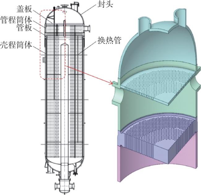
图1 等温反应器的三维模型(a)整体结构 (b)简化模型 Fig. 1 Three⁃dimensional model of the isothermal reactor |
表1 等温反应器的主要结构参数Table 1 Main structural parameters of the isothermal reactor |
| 反应器部件 | 长度/mm | 外径/mm | 内径/mm | 厚度/mm |
|---|---|---|---|---|
| 封头 | 4 200 | 4 000 | 100 | |
| 盖板 | 3 960 | 80 | ||
| 管程筒体 | 1 700 | 4 200 | 4 000 | 100 |
| 管板 | 4 300 | 435 | ||
| 壳程筒体 | 16 500 | 4 300 | 4 000 | 150 |
为提高数值模拟的计算效率,本文在建立等温反应器模型时作出如下简化和假设:(1)根据反应器结构的对称性,沿圆周方向建立1/4模型;(2)根据边缘效应,简化上封头的入水口、人孔接管、壳程筒体的长度;(3)由于换热管开孔焊接处的应力属于不连续应力,仅对很小局部区域有影响,此应力对管板整体强度影响不大,故不对换热管、填料管和热电偶管等管状结构进行建模;(4)将具有良好保温措施的壳程侧筒体外壁视为绝热边界。简化后的实体模型见图1 (b)。
1.2 控制方程
等温反应器的流固耦合计算涉及流体域和固体域之间的热量交换,在流-固交界面传热公式[9]为
式中:Kn 为固体导热系数,W/(m·K);T为温度,℃;q c为流体热通量,W/m2;h为对流传热系数,W/(m2·K);T l和T w分别为流体和壁面的温度,℃。
为了保持等温反应器中催化剂的温度基本恒定以及余热利用,在催化剂床层中布置大量竖直排列的套管式换热管,管程中饱和水吸收热量升温汽化,发生汽-液相变流动,故选用混合多相流模型,设置液态水和水蒸汽进行模拟计算。各相通过相间的连续性方程、动量方程和能量方程进行计算耦合[9],各方程如下。
连续性方程
动量方程
能量方程
式中:ρ为流体的密度,kg/m3;t为时间,s; v 为流体的速度矢量,m/s;f为单位体积流体受到的外力,N;p为压力,Pa;μ为动力黏度,Pa·s;E为单位质量的总能量,J/kg;q为热通量,W/m2;k为导热系数,W/(m·K)。
饱和压力是影响液态水相变过程的重要因素。等温反应器的换热管高度达17 m,不同管段内的静压强变化较为明显,为确保计算结果更加接近实际流动情况,使用安托尼(Antoine)方程拟合饱和水在管内各个高度位置的蒸发相变温度随压力的变化曲线,并代入计算模型,拟合方程为
式中:P为饱和蒸汽压,kPa。
1.3 换热管传热模拟及等温反应器参数设置
1.3.1 换热管工作参数及载荷施加方法
等温反应器的换热管是立式套管结构,265 ℃的饱和水自上而下从内管流入后在内管下端返回,吸收壳程的反应热并沸腾后流出。壳程催化反应的控制温度为320 ℃,等温反应器管程和壳程的操作压力分别为5 MPa和3.5 MPa。
等温反应器的模型结构和热载荷较为复杂,仅通过工作参数无法对等温反应器的温度场进行模拟,因此先单独进行换热管内流体沸腾传热模拟以求得换热管的出口温度及速度参数,再进行等温反应器整体模型的温度场模拟。分别使用温度载荷、对流载荷和流固耦合载荷模拟整体模型温度,其中温度载荷、对流载荷为简化载荷,仅需给定各热交换壁面的温度或传热系数,而流固耦合载荷为实际载荷,需要对管板附近的流体域进行流固耦合,换热管的出口条件即为流体域的入口条件。通过比较这3种热载荷模型的拟合结果,可为管板优化设计选出最合适的热载荷。
1.3.2 换热管内流体沸腾传热模拟
换热管的边界条件设置如下:(1)结合实际工作情况,模拟饱和水在重力驱动下的自然循环流动,得到换热管的入口参数;(2)出口边界条件设置为压力出口;(3)管外流体域模拟变换气恒温(320 ℃)反应,并与换热管外壁面发生对流换热。
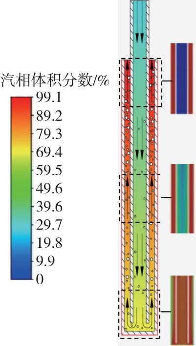
通过Fluent瞬态计算可知,管内流体自然循环流动在30 s后达到稳定状态,饱和水经换热管换热后,混合流体的平均温度由265 ℃升高到266.10 ℃,此时99.1%的水由液态转化为水蒸汽。图2 为管内相关管段的汽相云图,由于换热管的长径比过大,无法整体展示,故只截取重要部位的汽相云图。流体体积增加为流动提供动力,流体流出换热管时速度达到1.74 m/s。
1.3.3 热载荷模型设置
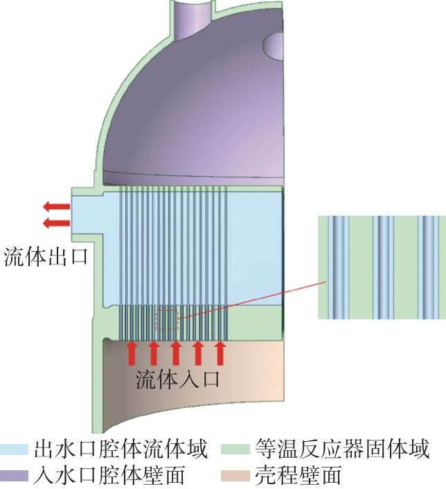
等温反应器在圆周方向均匀排布了4个入水口和出水口,根据反应器结构的对称关系可简化计算,取等温反应器的1/4结构进行建模。根据某公司提供的数据可知入水口腔体流场和壳程腔体流场状态较为稳定,故在计算流固耦合载荷模型时,将固体域与入水口腔体流场、壳程腔体流场的传热过程简化为固体域与恒定温度壁面的传热过程,以此提高计算效率。
在Steady⁃State Thermal模块中计算温度载荷模型和对流载荷模型的温度场,在Fluent模块中计算流固耦合载荷模型的温度场,等温反应器的各边界如图3 所示,热载荷参数设置如下。
(1)温度载荷模型(仅计算固体域)
入水口腔体壁面温度设置为265 ℃,出水口腔体壁面温度设置为266.10 ℃,壳程壁面温度设置为320 ℃。
(2)对流载荷模型(仅计算固体域)
各壁面温度与温度载荷模型相同,计算得到入水口腔体壁面、出水口腔体壁面、壳程壁面的对流传热系数分别为5 500、356、182 W/(m2·K)。
(3)流固耦合载荷模型
入水口腔体壁面温度设置为265 ℃、对流传热系数为5 500 W/(m2·K),壳程壁面温度为320 ℃、对流传热系数为182 W/(m2·K);以1.3.2节换热管流体沸腾传热的模拟结果为依据,将流体入口流速设置为1.74 m/s,入口温度设置为266.10 ℃,入口水蒸汽的体积分数设置为99.1%;设置出口边界条件为压力出口;流体与固体的交界面为耦合(coupled)壁面条件,流体域的环境压力为5.0 MPa。
确定模型热载荷的边界条件后,对3种模型施加相同的机械载荷(加载的作用力均通过等效计算得到):(1)对等温反应器的管程和壳程壁面分别施加5.0 MPa和3.5 MPa的压力;(2)对进水口和出水口分别施加371 999.10 N和463 900.46 N的压差作用力;(3)对等温反应器的管板换热管孔施加换热管拉力及其他力的联合作用力77 129.28 N;(4)对管板整体施加重力载荷;(5)对反应器的对称面施加无摩擦约束,壳程筒体下端部施加轴向0位移约束。
1.4 模型网格无关性验证
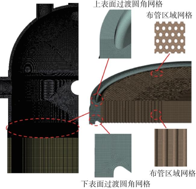
由于网格对于计算精度和时间有较大影响,因此对模型中不同结构有相应的形状和质量要求,具体如下:(1)管板为重点分析区域,根据管板结构特点对模型进行合理切分,将管板整体分割成两个几何体,并生成六面体网格(Solid186单元网格),以保证计算的准确性;(2)上封头、管程筒体、盖板和壳程筒体生成四面体单元网格,以保证网格在不同结构处的适应性。
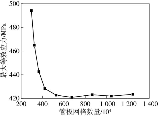
为保证3种热载荷模型网格计算的准确性,在确保管板以外区域网格数量相同的前提下,使用不同数量的网格对管板进行划分,并分别计算管板的最大等效应力,结果如图4 所示。可以看出,当网格数量从674万增加到865万时,最大等效应力的变化仅为2.3 MPa。综合考虑计算精度和周期,本文选取674万网格的管板进行仿真,网格模型如图5 所示。
1.5 模型有效性验证
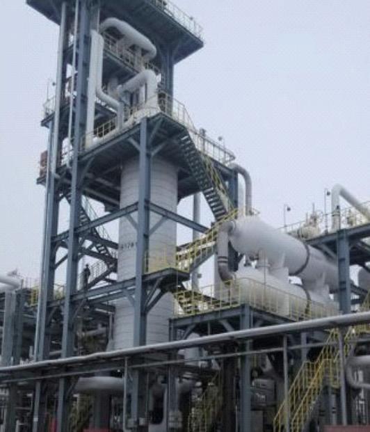
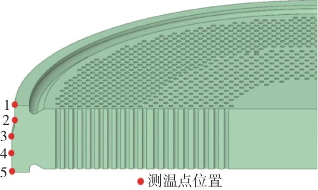
为验证3种不同热载荷所得温度场的准确性和有效性,在设备运行现场对等温反应器的管板外壁面温度进行测量,现场试验的等温反应器如图6 所示。在管板外壁面选取5个测点,使用5支TT-K-30型热电偶(OMEGA公司)采集温度(测温范围0~1 600 ℃),测点位置沿轴向均匀分布,如图7 所示。在反应器稳定运行时将温度数据导出到8401-21型温度数据记录仪(HIOKI公司)。
将实验测得的数据与3种热载荷模型计算得到的管板温度进行比较,结果如表2 所示。由表2 可得:温度载荷模型测点1、2、3的相对误差大于5%,对流载荷模型测点1的相对误差大于5%,这两种热载荷模型计算的管板温度与实测温度相差较大;流固耦合载荷模型所有测点的相对误差均小于5%,平均相对误差仅为1.63%,计算值与实验测得的管板温度场的吻合度较高。结果表明,这3种热载荷模型所有测点温度与实际温度间的相对误差均在10%以内,符合有效性要求。
表2 管板温度的实测值与模拟值比较Table 2 Comparison of measured and simulated values of tube sheet temperature |
| 测点位置 | 实测温度/℃ | 温度载荷 | 对流载荷 | 流固耦合载荷 | |||
|---|---|---|---|---|---|---|---|
| 温度/ ℃ | 相对误差/% | 温度/ ℃ | 相对误差/% | 温度/ ℃ | 相对误差/% | ||
| 1 | 297.2 | 268.5 | 9.66 | 282.1 | 5.08 | 306.2 | 3.03 |
| 2 | 302.9 | 275.5 | 9.05 | 291.7 | 3.70 | 309.0 | 2.01 |
| 3 | 308.1 | 283.8 | 7.89 | 298.3 | 3.18 | 311.5 | 1.10 |
| 4 | 314.0 | 306.8 | 2.29 | 307.2 | 2.17 | 316.1 | 0.67 |
| 5 | 315.6 | 320.0 | 1.39 | 320.0 | 1.39 | 319.8 | 1.33 |
2 结果与讨论
2.1 管板温度分布
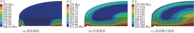
3种热载荷模型的管板温度分布云图(沿轴线旋转20°斜视图)如图8 所示。可以看出,从下表面(壳程侧)到上表面(管程侧)方向,管板由壳程热源温度逐渐降低至接近管程流体温度。3种热载荷模型得到的最低温度相差较大:温度载荷模型的最低温度为266.10 ℃,出现在管板布管区域和上表面;对流载荷模型和流固耦合载荷模型的最低温度分别为271.24 ℃和303.38 ℃,均出现在靠近管板的上表面布管区域。此外,温度载荷模型的最低温度区域面积最大,对流载荷模型次之,流固耦合载荷模型最小。
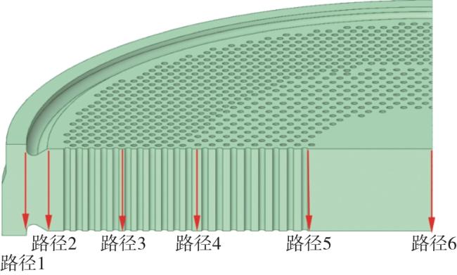
进一步量化分析不同热载荷模型对管板内部温度的影响规律,根据结构特征,选择在管板过渡区域设置路径1、2,管板布管区域设置路径3、4、5,管板中心位置设置路径6,管板路径选取如图9 所示(每条路径平均分布25个取值点)。从图9 中提取管板上不同路径的温度曲线,结果见图10 ,按照下式计算路径上的最大温度梯度[15]。
式中:GradT为温度梯度,℃/mm; 为温度插值,℃;d为距离,mm。
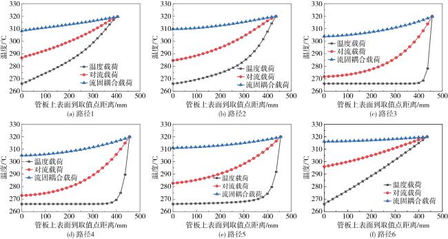
以上结果表明:(1)路径1、2处于管板壁面与布管区之间的过渡区域,温度载荷和对流载荷模型的路径1、2的温度梯度与布管区域路径3、4、5相比较为平缓;而流固耦合载荷模型的流体受过渡圆角结构的影响,其换热效率较高,该模型的过渡区域路径1、2与布管区域路径3、4、5的温度梯度接近;温度载荷、对流载荷、流固耦合载荷模型在过渡区域的最大温度梯度均出现在路径1上,分别为0.36、0.14、0.06 ℃/mm;(2)路径3、4、5处于布管区域,与换热管壁存在较大的热量交换,温度载荷和对流载荷模型的温度梯度较大,这两种热载荷模型布管区域的最大温度梯度均出现在路径3上,分别为1.78 ℃/mm和0.36 ℃/mm;而流固耦合载荷模型考虑了实际工况下管壁与流体的热量交换,该模型在布管区域的温度梯度远小于其他两种模型,其最大温度梯度出现在路径4上,仅为0.08 ℃/mm;(3)路径6处于管板中心区域,主要受管板上、下表面温度的影响,此时这3种热载荷模型的温度曲线均呈现线性变化,温度载荷、对流载荷、流固耦合载荷模型的最大温度梯度分别为0.15、0.07、0.02 ℃/mm;(4)3种热载荷模型在布管区域的温度梯度最大,过渡区域次之,中心区域的温度梯度最小。
结合实测温度和温度梯度进行分析,温度载荷和对流载荷模型假设温度和传热系数固定,导致管板温度的下降幅度较大,管板内部存在较为明显的温度梯度,与实际情况相差较大,不利于管板应力的准确计算。而流固耦合载荷模型考虑到流体的实际换热情况,管板温度梯度和上下表面的温差相对较小,管板温度分布合理,与实际情况相符,有利于管板应力的准确计算。
2.2 管板应力分布
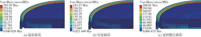
温度载荷、对流载荷、流固耦合载荷模型的管板等效应力分布如图11 所示,结果表明3种模型的应力集中区域均出现在管板表面的过渡圆角处,最大应力分别为282.39、243.27、206.81 MPa,最大应力值相差较大。
为分析不同热载荷模型对应力集中现象的影响,根据应力分布情况选择经过应力集中区域的路径1进行研究,其等效应力曲线如图12 所示。可以看出,3种热载荷模型在路径1的中间位置应力接近,随着取值位置向管板上、下表面靠近,应力差异逐渐增大。温度载荷、对流载荷、流固耦合载荷模型均在路径1的起始端(管板上表面处)出现等效应力最大值,分别为282.39、243.27、206.81 MPa;在路径1靠近中间的位置出现等效应力最小值,分别为19.29、18.70、18.35 MPa。
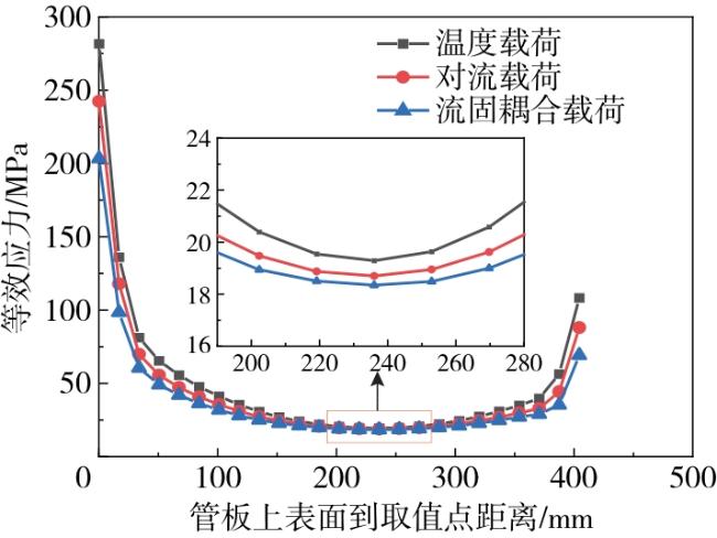
温度梯度使管板各相邻区域发生不同程度的变形,导致热应力产生。管板表面存在的过渡圆角可以提供一定的变形空间以吸收其他部位的热应力,使得应力在该区域集中释放,造成过渡圆角处所受热应力较大,并与管板其他力结合,产生应力集中现象。热应力计算如下[12]。
式中:σ为热应力,MPa;α为热通量材料的线膨胀系数,K-1;G为材料的弹性模量,MPa。从公式(7) 中可以看出在材料的线膨胀系数和弹性模量确定的情况下,热应力与温度梯度呈正相关。
结合图10 的温度曲线分析:温度载荷模型的温度梯度最大,管板所受热应力最大,导致管板应力集中现象明显;对流载荷模型的温度梯度次之,应力集中现象有一定缓解;流固耦合载荷模型的温度梯度最小,管板所受热应力最小,应力集中现象有较大缓解。
2.3 管板强度评估
为进一步研究不同热载荷模型对管板强度的影响,基于第三强度理论考虑管板材料的屈服和塑性变形情况,并根据JB 4732—1995(2005年确认)《钢制压力容器—分析设计标准》对管板局部薄膜应力和一次+二次应力进行强度分析与评定。管板结构不连续产生局部薄膜应力,过大的局部薄膜应力使管板局部结构发生塑性流动,载荷从高应力区传递至低应力区时产生过量塑性变形,导致管板局部结构被破坏。局部薄膜应力的评定标准[10]如下。
式中:P L为局部薄膜应力,MPa;K为载荷系数,取值为1;S m为设计应力强度(对应于常规设计下的许用应力),MPa。
一次应力是管板平衡压力与其他机械载荷所产生的法向应力或剪应力,包含薄膜应力与弯曲应力;二次应力是管板满足外部约束或自身变形的连续而产生的法向应力或剪应力。过大的一次+二次应力会使管板发生断裂。一次+二次应力的评定标准[10]如下。
式中:P b为弯曲应力,MPa;Q为二次应力,MPa。
在等效应力集中区域附近重新选取4条危险路径(图13 ),提取3种模型在4条路径上的局部薄膜应力和一次+二次应力。
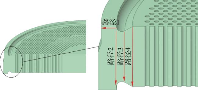
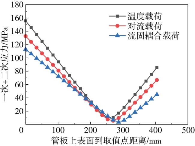
通过比较ANSYS模拟出的4条路径上的应力值可知,最大局部薄膜应力出现在路径1上,最大一次+二次应力出现在路径2上。不同热载荷模型下路径2的一次+二次应力曲线如图14 所示,最大局部薄膜应力和最大一次+二次应力如表3 所示。从图14 中可以看出,不同热载荷模型的一次+二次应力沿反应器厚度方向均呈现先减小后增大的趋势,并且在靠近过渡圆角一侧出现应力最大值。由表3 可知:相较于温度载荷模型,对流载荷和流固耦合载荷模型的最大局部薄膜应力分别降低了13.94%和23.71%,最大一次+二次应力分别降低了14.76%和27.54%,流固耦合载荷模型的应力降幅大于对流载荷模型;由这3种热载荷模型计算得到的应力值均远低于强度极限,管板存在较大的优化设计空间。
表3 不同热载荷模型的最大局部薄膜应力和最大一次+二次应力比较Table 3 Comparison of the maximum local film stress and the maximum primary + secondary stress of different thermal load models |
| 热载荷模型 | 最大局部薄膜应力/MPa | 最大局部薄膜 应力降幅a)/% | 局部薄膜应力 极限/MPa | 最大一次+二次 应力/MPa | 最大一次+二次应力降幅a)/% | 一次+二次应力 极限/MPa |
|---|---|---|---|---|---|---|
| 温度载荷 | 36.49 | 155.73 | ||||
| 对流载荷 | 31.40 | 13.94 | 265.80 | 132.74 | 14.76 | 531.60 |
| 流固耦合载荷 | 27.84 | 23.71 | 112.84 | 27.54 |
a—对流载荷和流固耦合载荷模型相较于温度载荷模型的降幅。 |
结合图10 (a)和图14 可得,温度梯度对等温反应器管板应力曲线变化趋势的影响较小,但对应力值的影响较大。局部薄膜应力和一次+二次应力与管板温度梯度呈正相关,即这两种应力随管板温度梯度的增加而增大。
通过上述分析可知,相较流固耦合载荷模型,温度载荷和对流载荷模型存在较大的温度梯度,计算得到的等效应力和局部应力均较大,其应力更接近强度极限,使得管板厚度的优化空间较小。而流固耦合载荷模型考虑了流体与结构之间的对流换热过程,精准获取了管板的温度梯度及各项应力值,因此基于流固耦合载荷进行模型优化设计的可靠度较高。
3 结论
本文通过数值模拟研究了温度载荷、对流载荷和流固耦合载荷模型对等温反应器管板温度场和应力场的影响,并采用压力容器规范标准对各模型的等效应力进行了强度评估,所得结论如下。
(1)相对于温度载荷和对流载荷模型,流固耦合载荷模型计算得到的等温反应器管板温度梯度最小,温度分布更符合实际情况。
(2)不同热载荷模型的等温反应器管板应力集中现象均出现在上表面圆弧过渡处,并且温度梯度越大,应力集中现象越明显;等温反应器管板的局部薄膜应力和一次+二次应力随管板温度梯度的增加而增大。
(3)相较于其他两种模型,流固耦合载荷模型更符合设备实际工况下的温度场分布及应力分布,得到的管板各项应力值均较低,强度评估结果较为准确,采用该模型对大型压力容器管板进行优化设计的可靠度最高。